|
The Ruskin House: Glued Laminated Beams, Sketches, Design, Calcs, Beginnings |
|
©2025 CALVINO architecture studio, inc all contents of this publication whether in digital or analog format are the express property of CALVINOarchitecture studio, inc. and shall not be reproduced by any means without written consent from Mike Calvino |
|
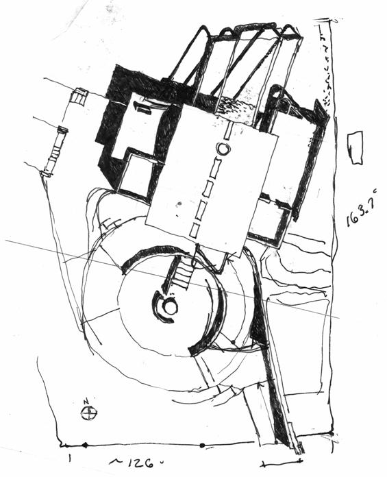
Initial Sketches |

|
. . . forge ahead . . . |
|
Glu-Lams, Initial sketches to Shop Drawings Glu-Lams, Fabrication |
|
Glu-Lams, Initial sketches to Shop Drawings |
|
Glu-Lams, Initial sketches to Shop Drawings |


|
The jigs at right . . . Below: cad model of jig/beam fabrication staging. |


|
Above: the last board of the first layer of the main glu-lams—these are approx. 53’ end to end.
Right: Planing the 1x8’s with the double planer set up. There is about 9,000 feet of 1x8 & they were passed an average of 3 times through the planer setup . . . That’s over 5 miles of 1x8 through the double planer! |

|
The layers are glued in place with a resorcinol, clamped to pressure and 2 rows of #8x1 1/2”, 304 stainless steel screws at 8”o.c. are run into each layer to maintain the clamping pressure. The clamps can be taken off as soon as the screws are in and the next piece can be started. |


|
Layer 3!
Above: the notch for the ceiling boards is cut into the second layer with an 8” dado blade on a table saw . . . A guide jig is clamped to the fence and table to keep the board running straight through the saw. |

|
Layer 20! |


|
Design Drawings |


|
Initial structural analysis for sizing and shaping, the shape is based on the moment forces with shear being minimum size at low moment forces. |
|
Further deflection and stress analysis using SpaceGass which was initially used to analyze the 2500pc steel rod space frame for an unbuilt gallery project. |
|
Above is the formwork for the main beams
Some connection design the curved forms, fabrication layout drawings. |
|
And a layer drawing after I planed the boards I had to draw all of the layers to see where to cut and trim each piece of each layer. Note the connection end of the beam at right in the drawing is still un-resolved . . . |