|
Back to Architecture Projects |
|
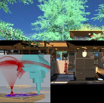
Some CAD model renderings from around 2010 |
|
Design Pages |
|
The project is conceived as a garden space under the Florida Live Oaks. It is defined by a textured masonry shell which is somewhere between primitive, carved stone masonry and a computer-generated code-image cast in concrete; and a floating roof plane that filters the sunlight. The masonry shell defines space, much as a ruin might be discovered, within the lot covered with the huge Oaks. The space is then covered by a perforated, floating plane that streams light through it like polka-dots of sunlight walking across the floor every day. The light comes from 46 custom designed and CNC fabricated, round skylights made from reclaimed stadium light lenses from the USF Sundome. These lenses are fitted to angled, cylindrical, sheet-steel tubes in cool, flat white. They allow more direct light into specific places in the winter and less direct light in summer, in order to control heat gain while still lighting the space without electricity during daylight hours. |







|
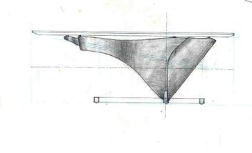
One of the first sketches of the project late 2007/early 2008. Sketching out the idea of the floating roof plane split into a north and south half, with a tower element at the north (to the right in this section). At far right of the sketch, there is the north property wall and some sort of screening element for privacy. The suspended kitchen concept can be seen at the center of the sketch as well as the idea of a screening concept separating private & public spaces with the service bar of spaces like kitchen, baths, laundry, storage. |
|
Below: the first and likely only working model of the project probably started around 2004 or so. The concept of constructing a superstructure over the existing house is here, as well as the idea of a “plinth” or raised floor defined and supported by two lines of large piers. This view of the model is from the Northeast or from the back of the property. The two giant live oaks can be seen in the model, the east one at the left of this photo, & the north one at the right. |

|
The concept in the early model shown in the view above about a sort of entry space under the live oak and stepping up onto the “plinth” is reflected in the later model view shown above to the right.
|

|
Right: early plan/model 2007 live/work concept |
|
Right: Final model/plan live/work concept realized with dividing “bar” of service spaces. |
|
Below: development of overhead plane as light filter to supplement the two live oaks. |
|
Right: early renders done in “Lightscape” textures not quite there yet, but not bad for 2007 with a model from ACAD. |
|
Below: view from the SE into the back yard over what was originally imagines as bamboo, but worked better as fishtail palms. |
|
Right: the “south colonnade” derived from the early spanish houses in St. Augustine. South exposure, shelterede entry area receiving low, direct sun in colder months. The colonnade is of queen palms to the right(south) & the MacBlock piers to the left(N). |
|
Right: Another early renderiing circa 2008 capturing the light quality a little better.
Below: Part of the structural study and analysis for the skylight can structures. 20ga galvanized sheet metal, CNC plasma cut & MIG welded. |
|
Below: A concept to meet the code lamp requirement for closet spaces and wet locations—lamps in each of the skylight cans to produce light from same source as during daylight hours. |
|
Right: the shop space, early rendering I believe in Rhino4 with Flamingo nXt. Used IvyGenerator to generate some of the plants. (geometry intensive) |
|
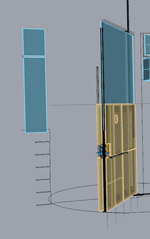
Below: CNC cutting layouts for the skylight can sheets. |
|
Right: early render of the north entry court. |


|
©2025 CALVINO architecture studio, inc all contents of this publication whether in digital or analog format are the express property of CALVINOarchitecture studio, inc. and shall not be reproduced by any means without written consent from Mike Calvino |

|
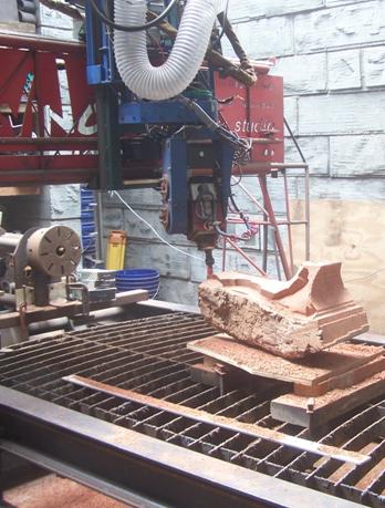
The Shell as a sort of ruin, defining general space to be used is made of concrete masonry units cast in cnc-carved forms abstracted from photographs of the live oak tree canopies. The sense imparted is one of ancient exact-ness, a sort of dichotomy ot time . . . Timeless. |
|
The double W14 steel beam supporting structure of the floating roof plane that is a light and air regulator is then perched within and atop the shell system on delicate, branch-like trussed supports with the intent that the supports blend into the background like small tree branches. |
|
The roof planes are then supported within the double W14 steel structure and is split and perforated to allow light and air to move through it and through the spaces below. The Steel structure slips in and out of the cypress clad floating planes, revealing itself much like the light and the wind. |




|
What is retained from the earliest sketch model is the concept of the definition of spaces between living spaces (living, sleeping) from the workspace (gathering, dining, studio, carport/workshop) by the use of a sort of solid bar of dense spaces which are more utilitarian. These dense space (the classical "poche space") being storage, laundry, bathrooms, a/c closets, kitchen, and eventually stair, are made of stud walls clad in a 3ft square, modular, birch plywood panel system and reads as a carved solid bar. The plan at right is an early plan circa 1997 showing the division of the original house into live/work spaces by the “solid bar” of the Laundry, kitchen, closets, and bathrooms with the living/sleeping space at the right(east) and the studio/workshop spaces at the left(west). |
|
Right: Skylight development summary |
|
Right: Plan of original home/studio |